Friday 24 May 2013

Bracket Design

For the bracket designs, we decided to look at a couple of different methods in order to come up with a variety of bracket options.

My design was looking at tubing, drawing inspiration from the Norton frame to come up with a design which matches the clean tubular curves of the frame. Using the AutoCAD drawing to define relationships between engine mounts and frame


Rear Brackets

Tubular bracket design, this gets welded to the cross bar.


The opposing bracket needs to be removable, bolting to the cross pipe, allowing the engine to be removed.


Cross bar, connecting two brackets.


Mounting points, connecting engine mount points to brackets.


Rear Bracket Assembly


Front Brackets

Based on similar principles as rear brackets. The left hand side front bracket is a singular curve which gets welded onto the cross bar.


The challenge with the front brackets is they are not symmetrical as the upper right hand side protrudes by 20mm.This meant having to separate the right hand side bracket into 2 separate brackets.

Lower Bracket


Upper Bracket


Both these brackets get bolted to the cross bar (creating the 20mm difference). These brackets are removable, like the right hand front bracket, allowing the engine be removed easily.

The cross pipe (joining the two sides of the brackets)gets welded to a cross bar on the frame.


Front Brackets in place.


Bracket Quotes

After finishing the design I sent the drawing off to a variety of manufacturers to get some quotes.

3D printing
I looked into 3D printing, uploading the models to Shapeways...


Steel Cold Bending

After receiving an expectedly high cost for 3D printing I looked into more traditional manufacturing methods. I sent quotes to various steel fabrication companies and only received a response from one, FJ Metal. FJ Metal specialize in steel cold bending.


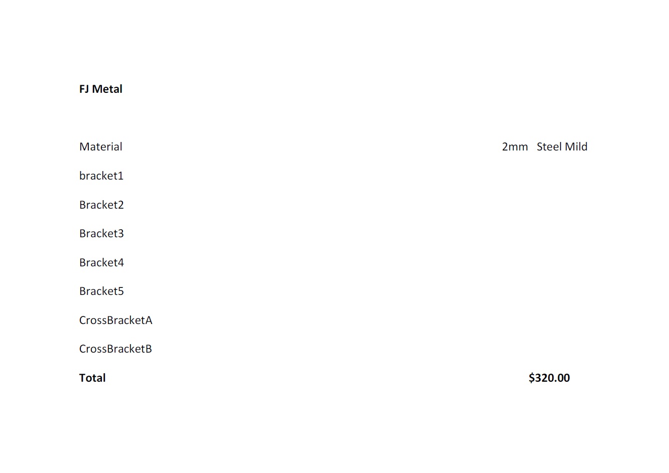
Though the steel cold bending method is not as accurate and is more labor intensive (welding etc. required)it would be a feasible choice if going ahead with bracket fabrication.

Tuesday 21 May 2013

Final Replication Modelling

Completion of my assigned modelling tasks accurately snapped together in one assembly.


With some added materials...

Remuneration Review

Revising Engine Position in Frame

As the photo stitched engine drawing wasn't an accurate aesthetic of the engine, Dan and Ben worked on combining the the frame and Alex's engine model in SolidWorks, placing it in a more desirable position (as discussed with Russell).


I then used this model and put it into AutoCAD, scaling it accordingly. This provided a more accurate elevation of the engine and it's position within the frame. This drawing means that we can take accurate measurements and model up our bracket designs on the same drawing as the engine and frame.

Friday 17 May 2013

Conflict Reviews

DCLD Group - Conflict

Presentation covered a broad range of content covering conflict. The visual presentation was very basic, consisting of a series of slides containing the written elements of the oral presentation. This meant the slides were quite dense with information; this perhaps could have been simplified into dot points. The act of simply reading off the visual presentation meant the overall impression was quite dry and lacked audience engagement. The examples used throughout were good and aided in the understanding of the topic though could've had more project specific examples to relate to the topic. Towards the end of the presentation some more project specific examples were used though examples could have been more in depth. Though there were project specific examples the concept of conflict in relation to collaboration was not fully addressed and could have been discussed further. Graphics used included a couple of graphs/charts which were used to outline different elements of conflict as well as resolution processes. Screen shots of the project were also used to aid in project specific examples.


Kinecting the Boxes - Conflict

The written presentation had simple dot points with interesting and clear visualisation. Tho oral presentation was clear and well spoken, though the speed in which the information was being presented lost engagement with the audience. The presentation contained a lot of information on the theme of conflict though it seemed a somewhat overload of information resulting in some of the main points being lost. Unfortunately the presentation only addressed interpersonal conflict, without including a broader application for conflict (e.g. hardware and software). Examples used throughout were helpful but there were only a couple of project specific examples, resulting in a weak conceptual link to the theme of collaboration. Images used were quite generic, not really aiding in understanding of their topic of conflict. Work was not referenced correctly.

Modeling Drive Chain

Using Measurements of technical drawing and motor to find position of engine sprocket in relation to the rear sprocket.


I then used these measurements to make a chain path.


Creating the engine sprocket by counting (and re counting) the number of teeth and measuring the radius. The accuracy of this was very important, having to ensure the distance between each tooth was the same as the distance between the teeth of the rear sprocket. I had to revise my measured radius slightly to ensure the circumference of the sprocket was evenly divisible by the distance between each tooth.


I then created an assembly starting with the rear sprocket/wheel and the engine sprocket. I placed these in position using the chain path and used the Belt/Chain feature to create the path for the chain.


I then measured up the chain elements to model the chain peices. This involved creating two models, one smaller/inner chain piece and one larger/outer chain piece.


Useful Chain Tutorial

I then used the two sizes of chain, alternating them along the chain path. Unfortunately I had troubles repeating the chain feature along the path using a pattern feature so I had to manually place and snap each piece of chain along the path.


An Hour Later.....


Sunday 12 May 2013

Sunday 5 May 2013

Modeling Reflection

Looking back on medeling techniques it is easy to identify areas which could have been done differently, or more accurately.

This is the case when looking at my initial method of creating the sprocket. It was brought to my attention that I didn't correctly use a circular form, therefore not creating semi circles between cogs. With the advise from Russell, I remodeled the sprocket teeth as follows:


I created a solid circular extrusion (overall shape of sprocket) and then created a semi circle void extrusion to create the distance between teeth.


I then created a circular pattern of the void extrusion to create the 45 teeth.


Then added a full round fillet to create the rounded shape of the teeth.

Saturday 4 May 2013

Milestone - Progress to Date

When looking at individual progress it is essential to look at our Group progress to see how our individual contributions can be assessed

Schedule:
Wk1
- Targeted CV

Wk2
- Developing Back Brief
- Establish Wiki & Facebook group

Wk3
- Deconstruction of Honda
- Photo stitch images of motor
- Download/Research SolidWorks

Wk4
- Begin modelling in SolidWorks
- Develop photostitch model

Wk5
- Modelling

Wk6
- Develop presentation on communication
- Modelling

Wk7
- Communication presentation
- Modelling

Wk8
- Review presentation
- Individual milestones
- Frame references (dimensions)
- Start Honda Frame

Wk9
- Finish Honda frame
- Design Brackets

Wk10
- Prototype development (Brackets)
- Clash detection
- Model assembly
- Create resources

Wk11
- Quotes (Featherbed frame, brackets, welding?)
- Research (for pdf links)

Wk 12
- Finish Wiki
- Group presentation
- Upload models (varied formats)
- Create pdf

This is a chart Ben made to visualise our progress to date and ensure we are on track


At this stage our groups progress seems to be going well and all seems to be on track to meet our project goals. We've tried to allow time for delays and any other details we have not considered. Individual Aim:
Working with an Agile development strategy means that our goals and responsibilities vary week to week. There are some weeks when the weighting of responsibility and work load are not evenly distributed but as a group and as individuals we are aware of this and are able shift workload amungst each other to ensure we are all putting in an equal effort overall. This is made easy by our teams motivation towards the project and willingness to contribute where needed.

My Major Milestone to date would be the completion of my assigned solid works models. This included learning how to use the program and model my allocated parts; rear sprocket, hub, rim, tire and front hub rim and tire. The task included modeling these components to a 2mm tolerance to ensure they are an accurate reflection of the real motorcycle parts. To ensure this accuracy I had to measure the dimensions of the physical components.

One of the most critical components to model is the rear sprocket, The position of the sprocket is vital in ensuring the relationship between the rear wheel and drive train. These measurements will be important in lining up the rear wheel and engine, as well as ensuring that the chain does not clash with any part of the featherbed frame.


The dimensions of the tires are also important in making sure the tires do not interfere with the frame (in width)allowing the wheel to rotate freely, similarly the height of the tire is important in ensuring to ensure vertical movement (in conjunction with swing arm) will not clash with frame.

Modeling Front Wheel

When it came to modeling the front wheel I used a similar concept to the rear wheel. The main differences include a smaller hub and disc brake.


CMS Parts For a Better Bike, Front Wheel - Disk schematic Honda Cb750f1 Super Sport 1976,http://www.cmsnl.com/honda-cb750f1-super-sport-1976-england_model14680/partslist/F08.html[Accessed 28/04/2013]


Though the process for the front wheel was the same as the rear wheel I had to adjust the hub, rim and tire sizes. The front rim has a greater diameter and is 10mm thinner, also meaning a thinner tire.

Thursday 2 May 2013

3D Modeling - Rear Wheel


After finishing the rear sprocket and hub I moved onto the rim and tire. The dimensions of the tires are important in making sure the tires don't interfere with the frame (in width)allowing the wheel to rotate freely, similarly the height of the tire is important in ensuring to ensure vertical movement (in conjunction with swing arm) will not clash with frame.

This process involved creating an accurate profile for the rim and revolving it 360 degrees.


Helpful tutorial for creating a rim: http://www.solidworkstutorials.com/solidworks-wheel/

Similarly I was able to make the tire. I made a profile as a rectangle of tire thickness and width, revolved it 360 degrees and created a a 3-sided full round fillet to create the shape of the tire.


Rear Sprocket/Wheel Animation