Considering how far the project has come and the skills I have learnt in CAM (SolidWorks)and the motorcycle field I think the project has been a success.
and am proud of what we have achieved.
Obviously there are ways in which the project could been improved, but we would not have been aware of this without
the knowledge that we have now. I think typical of a project of this nature we tried to 'bite off more than we could chew' and in the end ran out of time to develop a more in depth analysis of our approaches.
Some changes we might have made in hindsight:
-As a team we could have planned more by doing some more initial research into the field and consulting with people having greater industry knowledge.
-Perhaps by realising the the broader context of our project earlier on (creating an external resource) we would have started the grasshopper script for the featherbed frame earlier and been able to base more of our project on this concept of adapting and customising a frame.
-Though it was great learning experience to focus on a broad amount of content and various CAD and CAM techniques throughput the project, perhaps it would have been more beneficial to focus on a particular technique of CAM or be more selective of our outputs (parts we modeled). This may have resulted in a more in depth and comprehensive end result.
Sunday 2 June 2013
Individual Contribution
Major Contributions to the Project
Completion of SolidWorks Modeling
A major component of the project was to model up the various required parts of the motorbike(s) in SolidWorks. These models needed to be accurate to a 2mm tolerance to ensure the credibility of our models and our project as a whole.

My Modeled components Included:
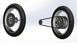
Rear Sprocket & Hub
Rear Rim & Tyre
Rear Drive Train
Front Hub, Rim & Tyre
Bracket Positioning
Motor Position
Motor Position Revised
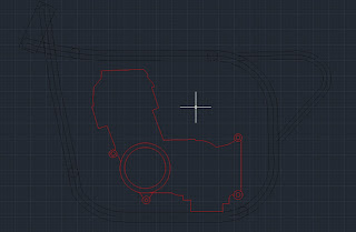
A major part of our project was the engine bracket design. Before we could start on the design we had to come up with a set position for the engine within the frame. Through discussions with Russell it became apparent that for this project the engine position was going to be based on aesthetics over functionality. I first drew a scaled 2D elevation of the motor and used an existing elevation of the featherbed frame, placing them together in AutoCAD. Using these drawings, in consultation with Russell, we were able to come up with an ideal position for the motor within the frame. We were then able to use this drawing to start the bracket designs.

Bracket Design
Bracket Design
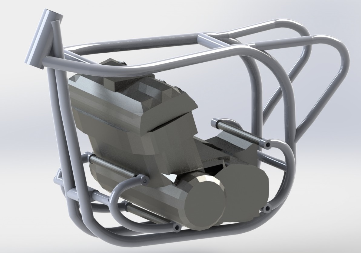
For the project I had to come up with a bracket design, the technique I looked at was tubing.
The design is based on the curves of the Norton frame, the brackets acting as an extension of the frame design.

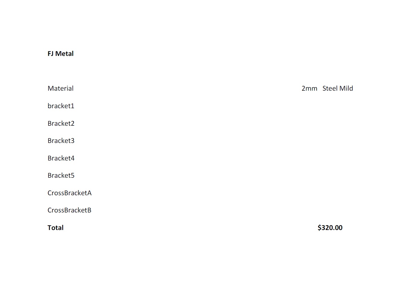
Part of the design process was looking at standards for tubing. I found that a standard tube for this type of job would have a 2mm wall and be made of mild steel. I then used this information to send inquiries for the brackets to get manufactured. I received a quote from FJ Metal for the Brackets to be made by cold bending for $320.
Final Assembly
Final Assembly
The process involved importing everyone's various model components and connecting them by "mating" them together in a final assembly. This was an interesting process as I had to look into how all the connections work and in our case sometimes didn't work; some of the parts weren't compatible. The whole process involved a lot of tweaking and repositioning of parts to accommodate relationships/connections between parts. Having an assembly model of the bikes components made it clear to identify the clashes within the model and proved a useful visual to what the bike would finally look like.

Completion of SolidWorks Modeling
A major component of the project was to model up the various required parts of the motorbike(s) in SolidWorks. These models needed to be accurate to a 2mm tolerance to ensure the credibility of our models and our project as a whole.

My Modeled components Included:
Rear Sprocket & Hub
Rear Rim & Tyre
Rear Drive Train
Front Hub, Rim & Tyre
Bracket Positioning
Motor Position
Motor Position Revised
A major part of our project was the engine bracket design. Before we could start on the design we had to come up with a set position for the engine within the frame. Through discussions with Russell it became apparent that for this project the engine position was going to be based on aesthetics over functionality. I first drew a scaled 2D elevation of the motor and used an existing elevation of the featherbed frame, placing them together in AutoCAD. Using these drawings, in consultation with Russell, we were able to come up with an ideal position for the motor within the frame. We were then able to use this drawing to start the bracket designs.

Bracket Design
Bracket Design
For the project I had to come up with a bracket design, the technique I looked at was tubing.
The design is based on the curves of the Norton frame, the brackets acting as an extension of the frame design.
Part of the design process was looking at standards for tubing. I found that a standard tube for this type of job would have a 2mm wall and be made of mild steel. I then used this information to send inquiries for the brackets to get manufactured. I received a quote from FJ Metal for the Brackets to be made by cold bending for $320.
Final Assembly
Final Assembly
The process involved importing everyone's various model components and connecting them by "mating" them together in a final assembly. This was an interesting process as I had to look into how all the connections work and in our case sometimes didn't work; some of the parts weren't compatible. The whole process involved a lot of tweaking and repositioning of parts to accommodate relationships/connections between parts. Having an assembly model of the bikes components made it clear to identify the clashes within the model and proved a useful visual to what the bike would finally look like.

Final Assembly Model
As one of my allocated tasks I was responsible for collating the various model components into a singular assembly to represent our final modeling output.

Rendered image of final assembly
The process involved importing everyone's various model components and connecting them by "mating" them together in the assembly. This was an interesting process as I had to think and in some cases research what part joins to what and how the various parts are connected. In some cases the connections didn't work as the parts were simply not compatible, so I simply placed them roughly in position. The whole process involved a lot of tweaking and repositioning of parts to accommodate relationships/connections between parts. Having an assembly model of the bikes components made it clear to identify the clashes within the model.

the most obvious and important clashes is with the drive train and the frame. This is due to the rear width of the Norton frame being smaller than that of the Honda. In order to resolve this problem the drive chain could be offset to the right by at least 12mm, allowing the chain 5mm clearance from the frame, however this would affect the balance of the motor and in turn affect performance.
Another clash is the Swing Arm and frame.As the rear frame dimensions of the bikes differ, the Honda swing arm does not fit within the Norton frame. This could be solved by modifying the frame or using an alternate swing arm (from a Norton).

Friday 24 May 2013
Bracket Design
For the bracket designs, we decided to look at a couple of different methods in order to come up with a variety of bracket options.
My design was looking at tubing, drawing inspiration from the Norton frame to come up with a design which matches the clean tubular curves of the frame. Using the AutoCAD drawing to define relationships between engine mounts and frame

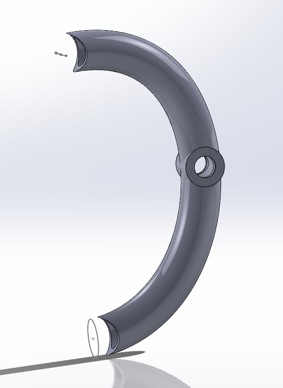
Rear Brackets
Tubular bracket design, this gets welded to the cross bar.

The opposing bracket needs to be removable, bolting to the cross pipe, allowing the engine to be removed.

Cross bar, connecting two brackets.

Mounting points, connecting engine mount points to brackets.

Rear Bracket Assembly

Front Brackets
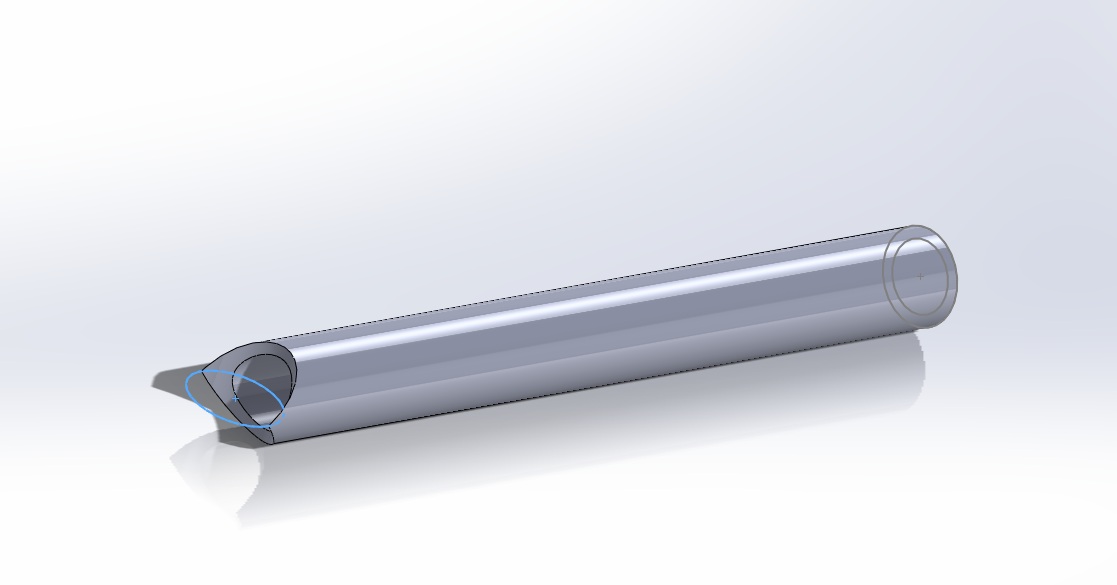
Based on similar principles as rear brackets. The left hand side front bracket is a singular curve which gets welded onto the cross bar.


The challenge with the front brackets is they are not symmetrical as the upper right hand side protrudes by 20mm.This meant having to separate the right hand side bracket into 2 separate brackets.
Lower Bracket

Upper Bracket

Both these brackets get bolted to the cross bar (creating the 20mm difference). These brackets are removable, like the right hand front bracket, allowing the engine be removed easily.
The cross pipe (joining the two sides of the brackets)gets welded to a cross bar on the frame.


Front Brackets in place.


Bracket Quotes
After finishing the design I sent the drawing off to a variety of manufacturers to get some quotes.
3D printing
I looked into 3D printing, uploading the models to Shapeways...

Steel Cold Bending
After receiving an expectedly high cost for 3D printing I looked into more traditional manufacturing methods. I sent quotes to various steel fabrication companies and only received a response from one, FJ Metal. FJ Metal specialize in steel cold bending.

Though the steel cold bending method is not as accurate and is more labor intensive (welding etc. required)it would be a feasible choice if going ahead with bracket fabrication.
My design was looking at tubing, drawing inspiration from the Norton frame to come up with a design which matches the clean tubular curves of the frame. Using the AutoCAD drawing to define relationships between engine mounts and frame

Rear Brackets
Tubular bracket design, this gets welded to the cross bar.

The opposing bracket needs to be removable, bolting to the cross pipe, allowing the engine to be removed.
Cross bar, connecting two brackets.
Mounting points, connecting engine mount points to brackets.

Rear Bracket Assembly

Front Brackets
Based on similar principles as rear brackets. The left hand side front bracket is a singular curve which gets welded onto the cross bar.


The challenge with the front brackets is they are not symmetrical as the upper right hand side protrudes by 20mm.This meant having to separate the right hand side bracket into 2 separate brackets.
Lower Bracket

Upper Bracket

Both these brackets get bolted to the cross bar (creating the 20mm difference). These brackets are removable, like the right hand front bracket, allowing the engine be removed easily.
The cross pipe (joining the two sides of the brackets)gets welded to a cross bar on the frame.


Front Brackets in place.


Bracket Quotes
After finishing the design I sent the drawing off to a variety of manufacturers to get some quotes.
3D printing
I looked into 3D printing, uploading the models to Shapeways...

Steel Cold Bending
After receiving an expectedly high cost for 3D printing I looked into more traditional manufacturing methods. I sent quotes to various steel fabrication companies and only received a response from one, FJ Metal. FJ Metal specialize in steel cold bending.
Though the steel cold bending method is not as accurate and is more labor intensive (welding etc. required)it would be a feasible choice if going ahead with bracket fabrication.
Tuesday 21 May 2013
Final Replication Modelling
Completion of my assigned modelling tasks accurately snapped together in one assembly.

With some added materials...

With some added materials...

Revising Engine Position in Frame
As the photo stitched engine drawing wasn't an accurate aesthetic of the engine, Dan and Ben worked on combining the the frame and Alex's engine model in SolidWorks, placing it in a more desirable position (as discussed with Russell).
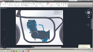
I then used this model and put it into AutoCAD, scaling it accordingly. This provided a more accurate elevation of the engine and it's position within the frame. This drawing means that we can take accurate measurements and model up our bracket designs on the same drawing as the engine and frame.

I then used this model and put it into AutoCAD, scaling it accordingly. This provided a more accurate elevation of the engine and it's position within the frame. This drawing means that we can take accurate measurements and model up our bracket designs on the same drawing as the engine and frame.

Friday 17 May 2013
Conflict Reviews
DCLD Group - Conflict
Presentation covered a broad range of content covering conflict. The visual presentation was very basic, consisting of a series of slides containing the written elements of the oral presentation. This meant the slides were quite dense with information; this perhaps could have been simplified into dot points. The act of simply reading off the visual presentation meant the overall impression was quite dry and lacked audience engagement. The examples used throughout were good and aided in the understanding of the topic though could've had more project specific examples to relate to the topic. Towards the end of the presentation some more project specific examples were used though examples could have been more in depth. Though there were project specific examples the concept of conflict in relation to collaboration was not fully addressed and could have been discussed further. Graphics used included a couple of graphs/charts which were used to outline different elements of conflict as well as resolution processes. Screen shots of the project were also used to aid in project specific examples.
Kinecting the Boxes - Conflict
The written presentation had simple dot points with interesting and clear visualisation. Tho oral presentation was clear and well spoken, though the speed in which the information was being presented lost engagement with the audience. The presentation contained a lot of information on the theme of conflict though it seemed a somewhat overload of information resulting in some of the main points being lost. Unfortunately the presentation only addressed interpersonal conflict, without including a broader application for conflict (e.g. hardware and software). Examples used throughout were helpful but there were only a couple of project specific examples, resulting in a weak conceptual link to the theme of collaboration. Images used were quite generic, not really aiding in understanding of their topic of conflict. Work was not referenced correctly.
Modeling Drive Chain
Using Measurements of technical drawing and motor to find position of engine sprocket in relation to the rear sprocket.

I then used these measurements to make a chain path.

Creating the engine sprocket by counting (and re counting) the number of teeth and measuring the radius. The accuracy of this was very important, having to ensure the distance between each tooth was the same as the distance between the teeth of the rear sprocket. I had to revise my measured radius slightly to ensure the circumference of the sprocket was evenly divisible by the distance between each tooth.

I then created an assembly starting with the rear sprocket/wheel and the engine sprocket. I placed these in position using the chain path and used the Belt/Chain feature to create the path for the chain.

I then measured up the chain elements to model the chain peices. This involved creating two models, one smaller/inner chain piece and one larger/outer chain piece.

Useful Chain Tutorial
I then used the two sizes of chain, alternating them along the chain path. Unfortunately I had troubles repeating the chain feature along the path using a pattern feature so I had to manually place and snap each piece of chain along the path.

An Hour Later.....

Sunday 12 May 2013


Sunday 5 May 2013
Modeling Reflection
Looking back on medeling techniques it is easy to identify areas which could have been done differently, or more accurately.
This is the case when looking at my initial method of creating the sprocket. It was brought to my attention that I didn't correctly use a circular form, therefore not creating semi circles between cogs. With the advise from Russell, I remodeled the sprocket teeth as follows:
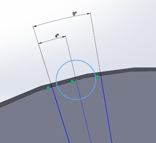
I created a solid circular extrusion (overall shape of sprocket) and then created a semi circle void extrusion to create the distance between teeth.

I then created a circular pattern of the void extrusion to create the 45 teeth.

Then added a full round fillet to create the rounded shape of the teeth.
Saturday 4 May 2013
Milestone - Progress to Date
When looking at individual progress it is essential to look at our Group progress to see how our individual contributions can be assessed
Schedule:
Wk1
- Targeted CV
Wk2
- Developing Back Brief
- Establish Wiki & Facebook group
Wk3
- Deconstruction of Honda
- Photo stitch images of motor
- Download/Research SolidWorks
Wk4
- Begin modelling in SolidWorks
- Develop photostitch model
Wk5
- Modelling
Wk6
- Develop presentation on communication
- Modelling
Wk7
- Communication presentation
- Modelling
Wk8
- Review presentation
- Individual milestones
- Frame references (dimensions)
- Start Honda Frame
Wk9
- Finish Honda frame
- Design Brackets
Wk10
- Prototype development (Brackets)
- Clash detection
- Model assembly
- Create resources
Wk11
- Quotes (Featherbed frame, brackets, welding?)
- Research (for pdf links)
Wk 12
- Finish Wiki
- Group presentation
- Upload models (varied formats)
- Create pdf
This is a chart Ben made to visualise our progress to date and ensure we are on track

At this stage our groups progress seems to be going well and all seems to be on track to meet our project goals. We've tried to allow time for delays and any other details we have not considered. Individual Aim:
Working with an Agile development strategy means that our goals and responsibilities vary week to week. There are some weeks when the weighting of responsibility and work load are not evenly distributed but as a group and as individuals we are aware of this and are able shift workload amungst each other to ensure we are all putting in an equal effort overall. This is made easy by our teams motivation towards the project and willingness to contribute where needed.
My Major Milestone to date would be the completion of my assigned solid works models. This included learning how to use the program and model my allocated parts; rear sprocket, hub, rim, tire and front hub rim and tire. The task included modeling these components to a 2mm tolerance to ensure they are an accurate reflection of the real motorcycle parts. To ensure this accuracy I had to measure the dimensions of the physical components.
One of the most critical components to model is the rear sprocket, The position of the sprocket is vital in ensuring the relationship between the rear wheel and drive train. These measurements will be important in lining up the rear wheel and engine, as well as ensuring that the chain does not clash with any part of the featherbed frame.

The dimensions of the tires are also important in making sure the tires do not interfere with the frame (in width)allowing the wheel to rotate freely, similarly the height of the tire is important in ensuring to ensure vertical movement (in conjunction with swing arm) will not clash with frame.

Modeling Front Wheel
When it came to modeling the front wheel I used a similar concept to the rear wheel. The main differences include a smaller hub and disc brake.

CMS Parts For a Better Bike, Front Wheel - Disk schematic Honda Cb750f1 Super Sport 1976,http://www.cmsnl.com/honda-cb750f1-super-sport-1976-england_model14680/partslist/F08.html[Accessed 28/04/2013]

Though the process for the front wheel was the same as the rear wheel I had to adjust the hub, rim and tire sizes. The front rim has a greater diameter and is 10mm thinner, also meaning a thinner tire.


CMS Parts For a Better Bike, Front Wheel - Disk schematic Honda Cb750f1 Super Sport 1976,http://www.cmsnl.com/honda-cb750f1-super-sport-1976-england_model14680/partslist/F08.html[Accessed 28/04/2013]


Though the process for the front wheel was the same as the rear wheel I had to adjust the hub, rim and tire sizes. The front rim has a greater diameter and is 10mm thinner, also meaning a thinner tire.

Thursday 2 May 2013
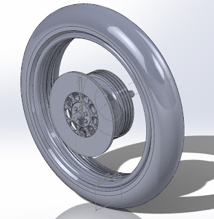
3D Modeling - Rear Wheel
After finishing the rear sprocket and hub I moved onto the rim and tire. The dimensions of the tires are important in making sure the tires don't interfere with the frame (in width)allowing the wheel to rotate freely, similarly the height of the tire is important in ensuring to ensure vertical movement (in conjunction with swing arm) will not clash with frame.
This process involved creating an accurate profile for the rim and revolving it 360 degrees.

Helpful tutorial for creating a rim: http://www.solidworkstutorials.com/solidworks-wheel/
Similarly I was able to make the tire. I made a profile as a rectangle of tire thickness and width, revolved it 360 degrees and created a a 3-sided full round fillet to create the shape of the tire.

Rear Sprocket/Wheel Animation
Monday 29 April 2013
Review on Communication
On the morning of our presentation we started to discuss our content which we had researched and how to turn this into a concise oral presentation. Through discussions it was made apparent that we had not fully considered the various connections between themes of communication and applying that to a collaborative environment.
Ironically enough this short discussion outlined just how essential regular face-to-face communication is within a collaborative environment.
We ended up discussing our topics and findings, feeding of each other and proposing ideas and various approaches to ensure we are being as relevant and comprehensive as possible.
This ensured our presentation was more concise and tailored to our project. As a result I've edited my topic information...
Communication Strategies
There are two main types of communication strategies; internal and external.
Internal
Due to the nature of collaboration, it was essential for our group to develop a cross communication strategy. This implicated a fluid communication network involving brainstorming and mind mapping to ensure an ideal collaborative work situation.
In establishing a communication strategy we need to look at our environment; we are a small team, working on a dynamic project with an experimental and agile development strategy. it is therefore even more essential to have an effective communication strategy to keep in contact with each other.
This kind of communication strategy lends itself to 'Passive Awareness', an indirect form of communication as all members of the group are being involved in all exchanges of communication. This adds to each individuals workload as more time is spent keeping up to date and aware of where all other team members are up to (e.g. uploading model updates).
In some cases the implication of our communication strategy involves spending more time strategising than actually implementing ideas, creating an ongoing cycle between strategy and implementation.
External
For our group external communication looks at how best to communicate our set of information to our target audience and how effective this is. This involves identifying our target audience and indentifying the best method of communicating with them (e.g. Bikers - do we add links to existing forums, tapping into a community that already exists?).
Our aim is to externally communicate a set of information accessible by a diverse range of people by offering various resources. these resources need to communicate information in a variety of different data forms which are simple to understand and easy to navigate through.
<
Communication presentation
For our presentation we choose the topic of communication, a topic which proves vital and very relevant to the nature of our project. We decided to think about how we could breakdown communication into sub categories in which we could individually work on. As a group we came up with 5 distinct categories to work on.
Topics for communication presentation:
Methods - Strategies, Structure Shaun
Platforms Andrea
Responsibilities - Personal Roles etc. Dan
Integrity/Performance - measurements, project communication performance Rebekah
Longevity - Relevance, Aims, Targeting Audience Alex
Ben is going to be responsible for filming and editing 3 min video outlining groups performance and reflection on topics of communication. This will be done as an interview style with each individual member talking about their topic.
From there we were able to individually research and write up some findings on our chosen topics and what they mean within a collaborative context, with specific reference to our project.
Once everyone completed their assigned task for the presentation I then compiled and edited the information into a single document for our final presentation....
Communication
For effective communication in a group project environment there are certain factors which need to be considered, including platforms, resources, HR, skills, roles, limitations, longevity etc in order to create an effective work environment and successful result.
Communication Strategies
In a typical hierarchical working relationships there are defined and independent communication paths between a leadership role and worker. For a collaborative environment it is essential to implement a cross-communicational team strategy. Within-team communication provides members with information about what their teammates are working on and where they are up to in the project development. When decisions and outcomes depend on the integration of different team member contributions it is important to be familiar with the tasks of fellow team mates to ensure a collaborative and comprehensive end result. This is particularly important for small teams or teams working with constantly changing environments or poorly defined outcomes (Fussell, S. 1998); something in which our group faces with roles and responsibilities continually being assessed and redefined throughout the project. It is therefore even more essential for us to focus on communicating directly to one another and include all participants in communication processes in order to achieve a successful outcome. Our group has achieved this style of communication by having many face-to-face meetings and setting up group communication platforms such as Facebook and Dropbox.
This type of group communication leads to increased passive awareness. "Passive awareness of what other team members are doing, provided by indirect participation in a communicative exchange...should enable a team member to better coordinate his/her activities with the rest of the team." (Fussell, S. 1998, p2) - Though this inter-team awareness is an important when dealing with a project such as ours it can also result in information overload; passive awareness consumes more of each individuals time and indirectly adds to an individual's work load. We face this problem on our Facebook group, were some posts are irrelevant to certain team members (e.g. querying measurements on a particular part of the bike that you are not working on). Using this type of team communication strategy lends to the group spending a lot of time on discussing ideas, concepts and solutions than actually implementing them.
Platforms
There are many methods of communication but for the context of our project we are looking at written communication, oral communication, face-to face and communication through media.
The benefits of written form is that as a team we have a physical record and reference of everything that was mentioned during discussion, these record also serve as evidence to avoid miscommunication or arguments amongst members in the future. Written communication can also avoid mistakes which can be made in interpreting other forms of communication (e.g. verbal)as it is a clearly defined communication medium.
Oral communication methods are also essential for teamwork, as members can provide and respond to each other’s feedback quickly and the issues and conflicts that occurred throughout the process of the project can be resolved through talking. Oral communication encourages flexibility as the method we have chosen to manage our team is one of Agile Development and therefore being able to communicate verbally helps us to understand each other’s idea's with greater understanding.
A face-to-face communication method directly corresponds with oral communication. This method is the most effective medium and has the greatest ability to communicate convince. Externally, face-to-face communication offers the opportunity to engage with our targeted audiences, creating a two-way relationship that enables the ability for audiences to respond.

Goodlife Evolution of Communication 2009 [online], Available from: http://www.goodlifeteam.com/wp-content/uploads/2009/05/evolution-of-communication.jpg [Accessed: 18.4.2013]
Perhaps the most powerful source of communication is social media; a form of networking which has the ability to reach the mass market with only a minimal input. The media world is limitless and is vitally important to our project as there is such dispersed target audience (Bikers & CAM enthusiasts). Social media offers the opportunity for anyone to comment, edit and embellish on our resources, enabling open dialogue and interaction between project and audiences.

GDNet Structuring your research 2013 [online], Available from: https://depot.gdnet.org/cms/gallery//27-iStock_000005622581Medium.jpg [Accessed: 18.4.2013]
Responsibilities
Design teams commonly include members from different design disciplines that must integrate their individual specialised knowledge in order to effectively and efficiently produce professional design solutions. Communication, including the integration of inter disciplinary specialised knowledge, has developed into a fundamental aspect of the collaboration design process. Individual team members have specific roles and responsibilities in ensuring that the communication process remains fluent and allows for the exchange of information and conflict resolution.
Leadership Responsibilities
Team leaders represent a significant component in the team design and communication process. The ability of the team leaders to communicate the direction and the organisational structure of the design team is vital to the success of the collaboration process. Design teams are increasingly required to work collaboratively in complex and dynamic environments which force them to constantly develop new team organisational structures and communication strategies. Team Leaders need to be able to adapt their communicational strategies to overcome challenges and obstacles in these dynamic team environments. The team leader’s main responsibilities during the team communication process include the communication of team goals, direction and culture, communicating project requirements and time schedules through division of individual tasks for completion and advising each team member of new decisions and resolving any issues arising from a communication breakdown.
Team Member Responsibilities
Team members need to be able to integrate their individual roles and responsibilities for the collective success of the design collaborative team. A common cause of failure for design teams is the inability to communicate the coordination of individual team member contributions to the given project. The roles and responsibilities of each team member will depend on a number of factors including the project requirements and their individual design discipline background. Although the main roles and responsibilities of each team member will differ from project to project. There are still a number of common responsibilities that are common to all projects which involve the team member having to communicate. These usually include the need for team members to communicate their individual knowledge, abilities and skills to both other team members and the team leadership, communicate constructive feedback on current team work and progress.

Wallpapers – 3D Business People, LORDOFDESIGN, viewed 17 April 2013, < http://lordofdesign.com/wp-content/uploads/2010/03/Wallpapers-3D-Business-People.jpg>

Speaking Male, Speaking Female – Communicating into Another’s Listening, image, Friedman, Will, Mental Help.Net, viewed 17 April 2013,
Communication Longevity
Communication plays a critical role in terms of keeping the project moving forward and the ongoing longevity of the project. Internal communication is vital as it allows team members to come together and keep them on target towards future goals within an allocated time frame. Without these small individual steps being taken, groups will struggle to finish their goal with higher quality work.

How to Use the Law of Attraction with Goal Setting, Bowen, D, viewed on the 19/04/13
To keep work focussed on the target audience teams must have a way of communicating externally with their target market. Some people may do this face to face, others through oral communication or even through an online forum. Having this form of communication with a reliable external source allows groups to gain first-hand knowledge from within the market itself.
Identifying Your Target Audience, Cordingley, D, viewed on the 19/04/13 < http://terrycordingley.blogspot.com.au/2012/06/day-2-identifying-your-target-audience.html>
Project Black is already looking beyond our group project, and how we can continue to develop our work for the future. As a group we have developed a wiki, whereby as both individuals and a team we are able to provide concise data to our target audience through the use of 3D models, analytical drawings and deconstruction videos. The space is a collection of data that provides not only the Honda CB750 community but also the motorcycle community as a whole, with a place to communicate, further their understanding or display jobs that are currently in progress or have been complete.
References
Fussell, S. Kraut, R. Lerch, J, et al. 1998, Coordination, overload and team performance: effects of team communication strategies , Human-Computer Interaction Institute Carnegie Mellon University, Pittsburgh pp. 2-6.
Weinrab, E. 2011, 10 Communication Strategies to Engage Employees in Sustainability [online], Available from: http://www.greenbiz.com/blog/2011/10/12/10-communication-strategies-engage-employees-sustainability [Accessed: 11.4.2013]
Acacio, V. 2012, The Benefits of Face-to-Face Communication [online], Available from: http://bluejeans.com/blog/benefits-face-to-face-meetings [Accessed: 11.4.2013]
Management Study Guide 2013, Written Communication- Meaning, Advantages and Disadvantages [online], Available from: http://www.managementstudyguide.com/written-communication.htm [Accessed: 18.4.2013]
Barrick, S, Stewart, G, 2000, ‘Team Structure and Performance: Assessing the Mediating Role of Intrateam Process and the Moderating Role of Task Type’, Academy of Management Journal, Vol 43, No. 2, pp. 135 – 148.
Sonnenwald, D, 1996, ‘Communication Roles that Support Collaboration during the Design Process’, Riso National Laboratory, Roskilde, Denmark, pp. 1 – 25.
Zaccaro, S, Riitman, A, Marks, M, 2001, ‘Team Leadership’, The Leadership Quarterly, Vol 12, pp. 451 – 483.
Katz, R, 1980, ‘The Influence of Group Longevity on Project Communication and Project Performance’, Administrative Science Quarterly, Vol. 27, No. 1(Mar., 1982), pp.81-104
Keller, R, 1982, ‘Predictors of the Performance of Project Groups in R & D Organizations’, The Academy of Management Journal, Vol. 29, No.4 (Dec., 1986), pp.715-726
Topics for communication presentation:
Methods - Strategies, Structure Shaun
Platforms Andrea
Responsibilities - Personal Roles etc. Dan
Integrity/Performance - measurements, project communication performance Rebekah
Longevity - Relevance, Aims, Targeting Audience Alex
Ben is going to be responsible for filming and editing 3 min video outlining groups performance and reflection on topics of communication. This will be done as an interview style with each individual member talking about their topic.
From there we were able to individually research and write up some findings on our chosen topics and what they mean within a collaborative context, with specific reference to our project.
Once everyone completed their assigned task for the presentation I then compiled and edited the information into a single document for our final presentation....
Communication
For effective communication in a group project environment there are certain factors which need to be considered, including platforms, resources, HR, skills, roles, limitations, longevity etc in order to create an effective work environment and successful result.
Communication Strategies
In a typical hierarchical working relationships there are defined and independent communication paths between a leadership role and worker. For a collaborative environment it is essential to implement a cross-communicational team strategy. Within-team communication provides members with information about what their teammates are working on and where they are up to in the project development. When decisions and outcomes depend on the integration of different team member contributions it is important to be familiar with the tasks of fellow team mates to ensure a collaborative and comprehensive end result. This is particularly important for small teams or teams working with constantly changing environments or poorly defined outcomes (Fussell, S. 1998); something in which our group faces with roles and responsibilities continually being assessed and redefined throughout the project. It is therefore even more essential for us to focus on communicating directly to one another and include all participants in communication processes in order to achieve a successful outcome. Our group has achieved this style of communication by having many face-to-face meetings and setting up group communication platforms such as Facebook and Dropbox.
This type of group communication leads to increased passive awareness. "Passive awareness of what other team members are doing, provided by indirect participation in a communicative exchange...should enable a team member to better coordinate his/her activities with the rest of the team." (Fussell, S. 1998, p2) - Though this inter-team awareness is an important when dealing with a project such as ours it can also result in information overload; passive awareness consumes more of each individuals time and indirectly adds to an individual's work load. We face this problem on our Facebook group, were some posts are irrelevant to certain team members (e.g. querying measurements on a particular part of the bike that you are not working on). Using this type of team communication strategy lends to the group spending a lot of time on discussing ideas, concepts and solutions than actually implementing them.
Platforms
There are many methods of communication but for the context of our project we are looking at written communication, oral communication, face-to face and communication through media.
The benefits of written form is that as a team we have a physical record and reference of everything that was mentioned during discussion, these record also serve as evidence to avoid miscommunication or arguments amongst members in the future. Written communication can also avoid mistakes which can be made in interpreting other forms of communication (e.g. verbal)as it is a clearly defined communication medium.
Oral communication methods are also essential for teamwork, as members can provide and respond to each other’s feedback quickly and the issues and conflicts that occurred throughout the process of the project can be resolved through talking. Oral communication encourages flexibility as the method we have chosen to manage our team is one of Agile Development and therefore being able to communicate verbally helps us to understand each other’s idea's with greater understanding.
A face-to-face communication method directly corresponds with oral communication. This method is the most effective medium and has the greatest ability to communicate convince. Externally, face-to-face communication offers the opportunity to engage with our targeted audiences, creating a two-way relationship that enables the ability for audiences to respond.

Goodlife Evolution of Communication 2009 [online], Available from: http://www.goodlifeteam.com/wp-content/uploads/2009/05/evolution-of-communication.jpg [Accessed: 18.4.2013]
Perhaps the most powerful source of communication is social media; a form of networking which has the ability to reach the mass market with only a minimal input. The media world is limitless and is vitally important to our project as there is such dispersed target audience (Bikers & CAM enthusiasts). Social media offers the opportunity for anyone to comment, edit and embellish on our resources, enabling open dialogue and interaction between project and audiences.

GDNet Structuring your research 2013 [online], Available from: https://depot.gdnet.org/cms/gallery//27-iStock_000005622581Medium.jpg [Accessed: 18.4.2013]
Responsibilities
Design teams commonly include members from different design disciplines that must integrate their individual specialised knowledge in order to effectively and efficiently produce professional design solutions. Communication, including the integration of inter disciplinary specialised knowledge, has developed into a fundamental aspect of the collaboration design process. Individual team members have specific roles and responsibilities in ensuring that the communication process remains fluent and allows for the exchange of information and conflict resolution.
Leadership Responsibilities
Team leaders represent a significant component in the team design and communication process. The ability of the team leaders to communicate the direction and the organisational structure of the design team is vital to the success of the collaboration process. Design teams are increasingly required to work collaboratively in complex and dynamic environments which force them to constantly develop new team organisational structures and communication strategies. Team Leaders need to be able to adapt their communicational strategies to overcome challenges and obstacles in these dynamic team environments. The team leader’s main responsibilities during the team communication process include the communication of team goals, direction and culture, communicating project requirements and time schedules through division of individual tasks for completion and advising each team member of new decisions and resolving any issues arising from a communication breakdown.
Team Member Responsibilities
Team members need to be able to integrate their individual roles and responsibilities for the collective success of the design collaborative team. A common cause of failure for design teams is the inability to communicate the coordination of individual team member contributions to the given project. The roles and responsibilities of each team member will depend on a number of factors including the project requirements and their individual design discipline background. Although the main roles and responsibilities of each team member will differ from project to project. There are still a number of common responsibilities that are common to all projects which involve the team member having to communicate. These usually include the need for team members to communicate their individual knowledge, abilities and skills to both other team members and the team leadership, communicate constructive feedback on current team work and progress.

Wallpapers – 3D Business People, LORDOFDESIGN, viewed 17 April 2013, < http://lordofdesign.com/wp-content/uploads/2010/03/Wallpapers-3D-Business-People.jpg>

Speaking Male, Speaking Female – Communicating into Another’s Listening, image, Friedman, Will, Mental Help.Net, viewed 17 April 2013,
Communication Longevity
Communication plays a critical role in terms of keeping the project moving forward and the ongoing longevity of the project. Internal communication is vital as it allows team members to come together and keep them on target towards future goals within an allocated time frame. Without these small individual steps being taken, groups will struggle to finish their goal with higher quality work.

How to Use the Law of Attraction with Goal Setting, Bowen, D, viewed on the 19/04/13
To keep work focussed on the target audience teams must have a way of communicating externally with their target market. Some people may do this face to face, others through oral communication or even through an online forum. Having this form of communication with a reliable external source allows groups to gain first-hand knowledge from within the market itself.

Identifying Your Target Audience, Cordingley, D, viewed on the 19/04/13 < http://terrycordingley.blogspot.com.au/2012/06/day-2-identifying-your-target-audience.html>
Project Black is already looking beyond our group project, and how we can continue to develop our work for the future. As a group we have developed a wiki, whereby as both individuals and a team we are able to provide concise data to our target audience through the use of 3D models, analytical drawings and deconstruction videos. The space is a collection of data that provides not only the Honda CB750 community but also the motorcycle community as a whole, with a place to communicate, further their understanding or display jobs that are currently in progress or have been complete.
References
Fussell, S. Kraut, R. Lerch, J, et al. 1998, Coordination, overload and team performance: effects of team communication strategies , Human-Computer Interaction Institute Carnegie Mellon University, Pittsburgh pp. 2-6.
Weinrab, E. 2011, 10 Communication Strategies to Engage Employees in Sustainability [online], Available from: http://www.greenbiz.com/blog/2011/10/12/10-communication-strategies-engage-employees-sustainability [Accessed: 11.4.2013]
Acacio, V. 2012, The Benefits of Face-to-Face Communication [online], Available from: http://bluejeans.com/blog/benefits-face-to-face-meetings [Accessed: 11.4.2013]
Management Study Guide 2013, Written Communication- Meaning, Advantages and Disadvantages [online], Available from: http://www.managementstudyguide.com/written-communication.htm [Accessed: 18.4.2013]
Barrick, S, Stewart, G, 2000, ‘Team Structure and Performance: Assessing the Mediating Role of Intrateam Process and the Moderating Role of Task Type’, Academy of Management Journal, Vol 43, No. 2, pp. 135 – 148.
Sonnenwald, D, 1996, ‘Communication Roles that Support Collaboration during the Design Process’, Riso National Laboratory, Roskilde, Denmark, pp. 1 – 25.
Zaccaro, S, Riitman, A, Marks, M, 2001, ‘Team Leadership’, The Leadership Quarterly, Vol 12, pp. 451 – 483.
Katz, R, 1980, ‘The Influence of Group Longevity on Project Communication and Project Performance’, Administrative Science Quarterly, Vol. 27, No. 1(Mar., 1982), pp.81-104
Keller, R, 1982, ‘Predictors of the Performance of Project Groups in R & D Organizations’, The Academy of Management Journal, Vol. 29, No.4 (Dec., 1986), pp.715-726
Subscribe to:
Posts (Atom)